Radiator Shutters

|
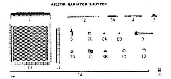
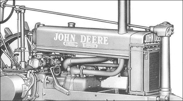
Part #2 is the operating bar. It has holes in it for the slats (#11). When this bar moves back and forth, the slats open and close. Notice the little stud sticking up from the middle of it. Two things attach to that stud: the spring (#3A), and the operating link (#4). Now look in the photo and you can see them just behind the steering post. The OTHER end of the link is attached to the bell crank (#5). The bell crank pivots on a bracket (#6) on the corner of the shutter assembly. See it?? The other side of the bell crank is attached to the control rod (#14). The crank is what allows the motion of the linkage to "turn the corner". The control rod is usually attached to the side of the hood with a guide clip (#15), although this photo doesn't show one. The rear end of the control rod is, of course, attached to the control lever (#9) with an adjustable end (#13). Part #12 is the bracket for the control handle.
And there you HAVE it!! |
| |

"Those Oldies But Goodies"
Little Caesar and the Romans, 1961
Go back to the page you just came from......
Or... Go back to the SCHOOL page, HERE
